Weather Protection
Anabat is often used for passive monitoring, when a detector is placed in the field and left there for weeks, months or years without human intervention, except for occasional downloading or servicing. Such systems require protection from the weather, so the electronic components are protected from rain. There is a greater issue here, because rain is not the only hazard - biofouling, vandalism, ice, extreme heat, etc are all factors which can degrade detector performance, or destroy equipment. But this page will concentrate on rain, which is by far the commonest problem. Basically, except for overnight deployments, rain protection is always essential.
Different Types of Protection
There are several ways your equipment can be protected from the rain. Many users have employed simple cones or umbrella type protection, where the assumption is that the rain will come from a predictable direction and if you orient the microphone away from that direction, or keep it under some kind of shelter, then damage will be prevented. But in most climates, these are not very realistic assumptions, so I will concentrate here on methods which afford a good deal of rain protection without making any assumptions about how heavy the rain will be, or where it will come from. The main methods which have been used are pipes, reflectors and membranes.
Membranes
The concept is simple enough - shield the equipment with some sort of membrane which lets the sound through but keeps the rain out. The advantage of the membrane approach is its simplicity - but it also benefits from the fact that a membrane such as thin plastic (eg "Glad Wrap") does not make a very favorable habitat for the kinds of animals which tend to mess up bat detectors, because the membrane surface is shiny and smooth and doesn't really provide anything very useful from a wild animal's point of view.
The main problem with a membrane is that the sorts of membranes which let sound through well, aren't very good at keeping out rain. Or even if they are, they might stay wet for extended periods after a soaking, affecting sound transmission even more. Tests I have done show that a thin membrane of "GladWrap" imposes about 10 to 20 dB of attenuation. Such attenuation might have relatively little effect on detection of bats which are easy to detect from a distance, because atmospheric attenuation becomes the main factor affecting how far a bat can be detected. But for quieter bats, this could represent a severe performance penalty. Furthermore, if the membrane is close to the microphone, there are likely to be resonances set up because the sound can bounce back and forth between the membrane and the microphone. Such resonances might not have too much effect on bat detection, but they will probably make it more difficult to achieve consistency between different passive monitoring units, because the nature of a resonance is likely to be fairly sensitive to subtle variations in geometry.
Even so, membranes might have a place. In situations where absolute sensitivity is not too much of an issue (and these are quite common - think how often you will turn down the sensitivity of a detector for passive monitoring purposes), and where unit to unit variation is tolerable, the advantages of a simple system which is relatively immune from biofouling might make it attractive.
There are other possibilities. A flywire screen lets sound through well (though I haven't yet done rigorous tests of this), and if the detector is far enough back from the screen, it could afford effective protection from rain, because the rain will tend to run down the screen rather than passing straight through. There may be situations where this very simple approach should be considered, for example where a detector will be housed inside a building with fly-wire screens which are not covered by closeable windows. An example which comes to mind is that many buildings in inland Australia, such as shearers' quarters, often have verandas which are completely enclosed by screens to keep flies and mosquitoes out. A detector placed on a table on the veranda, well back from the screen, will do a tolerable job of recording the local bat fauna straight through the screen. Without any hard evidence, I suspect performance will be best if the detector is oriented at right angles to the screen, so in the above case, the detector should be horizontal and facing straight outwards.
Pipes
Curved pipes have often been used to deflect sound upwards into a microphone which is out of reach of the rain. This approach is simple and effective, and it has been used by many people in many different manifestations.
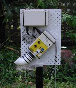
In the above picture, you can see a simple manifestation which I was able to put together very quickly and at very little cost. The detector and ZCAIM are mounted on a pegboard backplate with a combination of cable ties (for strength) and adhesive backed Velcro tape (to keep things in place better). The pipe has a diameter a little larger than the microphone, which fits snugly into it. The pipe bends gently through 90 degrees. I have found that pipes with abrupt angle changes tend to degrade recording quality. At its lowest point, the pipe contains a small hole drilled through to let any water out. This won't work by itself, because surface tension prevents the water from flowing through the hole. But with a thread of fine cotton running through the hole, it seems to drain effectively. I simply ran the cotton in a loop through the hole and back into the open end of the tube. The whole assembly is wrapped in a thick sheet of polythene which is tied at the bottom in such a way that it protects everything from rain but does not obscure the pipe opening. A point to remember is that the polythene needs to be wrapped tightly and care taken to make sure it can't flap around in a breeze, because that would create a lot of ultrasonic noise. Note that the detector is pointing down at 45 degrees, but its main axis of detection is effectively facing upwards at 45 degrees.
Pipes do affect frequency response by creating little resonances which tend to have more effect at higher frequencies. In one set of tests, I found a significant loss of sensitivity at frequencies above about 40 kHz. Whether or not this is a problem will depend on the range of bats being monitored, and it may vary greatly with pipe geometries. Overall, though, they work well for the frequency range where most species are found, provided the pipe is large enough in diameter and doesn't bend too abruptly.
Reflectors
The most widely used method of weather protection is a simple reflector to deflect the sound up into a microphone which is protected from the rain.
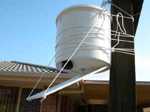
Here's a very simple version which can be put together very quickly and cheaply. All the electronics are placed inside a sealable plastic bucket, with a hole cut in the bottom to let the microphone out near the outer edge. The microphone will get wet in a heavy rain, but only on the outside where it doesn't matter. The reflector in this case is a plastic cutting board, but this one was smoother than most. A cake pan or any other smooth, flat plate could be used. It doesn't matter much what it is made of, as long as it is smooth, flat and sufficiently rigid.
In the Bat Bucket above, the angle of the reflector has been chosen so the main axis of detection (the beam) is facing upwards at about 45 degrees, while the microphone is facing straight downwards. Remember that angle of incidence equals angle of reflection and you can easily figure out the angles. But it is a bit more complex, because you don't want too much of the beam obscured by the bucket, which is why the microphone is placed near the outer edge. The beam varies in angular width with the frequency of the incoming sound, and it doesn't have sharp edges anyway, but in practice, it is useful to think of the beam as 45 degrees wide (22.5 degrees either side of the central axis). You should therefore try to ensure that all of that beam falls onto the reflector plate, and that it doesn't reflect back up into the bucket. This is easiest with a reflector which is at 45 degrees to the microphone axis, and that is the ideal setup if it is desired to end up with a horizontal beam, because then the detector faces straight downwards and the reflector is 45 degrees from the horizontal. But if you want a beam which points up at 45 degrees, it is a little less ideal, because then the reflector is horizontal and the detector points down at 45 degrees. This has two main consequences: 1) if the detector is close enough to the reflector, then rain will actually bounce up off the reflector into the microphone, and 2) a horizontal reflector isn't so good at shedding water and other fouling.
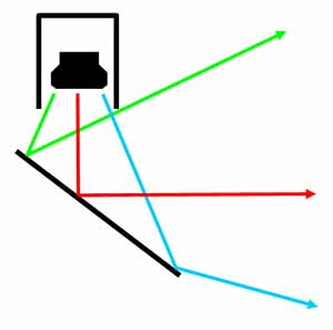
The above diagram shows the geometry for the 45 degree reflector case where the reflector is at 45 degrees to the main axis of the microphone. With the microphone pointing down, the beam ends up horizontal. Note that the upper ray (green) just misses the microphone housing if the geometry is worked out well. By rotating this scheme 45 degrees anticlockwise, you get a horizontal reflector and a beam going up at 45 degrees.
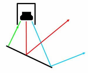
In this case, the reflector is at 22.5 degrees from the horizontal, so a microphone facing straight down ends up with a beam rising at 45 degrees to the horizontal. In this case, the green ray is reflected straight back at the microphone, indicating that some portion of the beam is lost because the microphone and its housing get in the way. Note that the detector needs to be further away from the reflector in this arrangement.
Reflectors work extremely well . There is very little loss of sensitivity along the main axis, though there will be some loss of overall detection volume because not all of the beam is actually useable. There are a few general principles to bear in mind.
1) Greater distances between microphone and reflector reduce the chance of rain reflecting up into the microphone (to a limited extent, rain drops bounce just like sound) and also reduce the shading of the beam by the microphone and its housing. However, greater distances also require larger reflectors, making them less portable and more subject to problems from wind.
2) It s very important that if you have the microphone connected to the detector by a cable, that water cannot run down the cable into the back of the microphone housing. This is very destructive to the microphone!
3) You could use curved reflectors to alter the beam shape. This might have advantages in some cases, but it will also make it more difficult to achieve consistency between units. Many people think they might get advantages by using a parabola, in much the same way that people recording bird sounds will use a parabola. However, in order to do that, you need to match the parabola to the beam shape of the detector (which varies with frequency). A parabola is best suited to a microphone with a broad beam, because a small beam requires a longer distance between microphone and parabola in order to use the whole surface of the parabola. But more importantly, the effect of using a parabola would be to make the beam narrower. This would theoretically allow you to detect bats from further away, but over a narrower angular range, which means the volume of detection might be seriously reduced. Furthermore, for bats which are already detectable over substantial distances, there is little to gain, because increasing the gain in a particular direction achieves little improvement in maximum detection distance, which is mostly affected by atmospheric attenuation. Overall, I don't think there's much point in using curved reflectors, but there may be specific tasks for which it might be useful. It is possible to increase the gain of the microphone by using reflectors or horns, but only at the cost of its beam width.
On the other hand, there might be situations in which it would be advantageous to use a curved reflector (convex to the microphone) to REDUCE directionality. The general principle would be to spread out the central lobe of the microphone's response so that instead of going for distance, it accepts sound from a wider angular range. A smooth cone pointed straight at the detector might perform this function. A sphere would likely be less effective, because much of the central lobe would be reflected straight back into the microphone. But imagine a detector pointing straight downwards at a cone whose tip was pointed straight back at the detector. My guess is that it would need to be a fairly flat cone, and it should occupy about 45 degrees as seen from the microphone, so it intercepts much of the microphone's beam. The effect of such a device will be to reduce the distance at which bats can be detected, but there might still be significant gain in the volume within which bats could be detected. I can imagine this being useful for low intensity bats flying close to the detector, but I haven't tried it.
A word about "cones of reception"
In the diagrams above I have represented the beam as a cone spreading outwards. But this is only true in a very crude sense. If you consider the zone of reception in terms of how far away you can detect a bat at any given angle, then you find the detector is most sensitive straight along its main axis. The actual shape of the zone of reception depends greatly on the frequency of the sound, but also on its intensity and on the weather. But in general, rather than a cone broadening outwards, it would be more accurate to view it as a cone with the pointy end outwards.
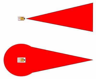
Neither of the above diagrams is accurate at all, but the bottom one is much closer to the truth! The main consequence is that a bat in the distance can only be detected if it is nearly in line with the main axis of the microphone. But there is another, more subtle consequence. The "frontal lobe" along the main axis where the detector is most sensitive is quite narrow at most ultrasonic frequencies, so even though that is where a bat can be detected from the greatest distance, it doesn't contribute all that much to the overall volume in which a bat can be detected. So, while it is true that the detector is much more directional at higher frequencies, in a subtle way, this often isn't true. In fact, for a reasonably loud bat calling at fairly high frequencies, such as many Pipistrelles, the frontal lobe is so narrow that it contributes very little to the overall volume of detection, so the nett effect is that the detector is almost omnidirectional!
The impact of this subtlety is different depending on how the detector is being used. If you are actively monitoring, then you tend to point the detector towards a bat, so what is more important is the distance at which you can detect it. In that case, for higher frequencies, the detector is more directional. But for passive monitoring, where a bat could be recorded at any direction from the detector, the frontal lobe is less significant, and directionality can actually increase at lower frequencies. This is especially true if the detector is raised up off the ground, because then it is possible to detect a bat from all directions.
Taking the microphone off the detector
In many situations, it might be useful to remove the microphone from the detector and connect it via a cable. This makes it easier to protect the more expensive parts of the system, while reducing the size of containers which need to be mounted. Furthermore, it reduces the size of the package containing the microphone, and therefore reduces the portion of the microphone beam which is intercepted by that package. Microphones have been successfully removed by several tens of metres in some cases, giving the advantage that the detector and its controls can be available while the microphone is way out of reach.
If a standard microphone is used off the detector, it should be connected with only a short cable, certainly no more than 2 metres and preferably less. The reason is that the cable attenuates higher frequencies when used in this way. The Lo-Mic (with an enhanced low frequency response) and the Hi-Mic (designed to be used with a longer cable) both have lower impedance drivers that are more suitable for driving cables of greater length. It is also possible to get cables made up with special line driving preamplifiers which give even better results.
In some tests I ran, I found the standard microphone showed no loss of sensitivity with a 1 metre cable, but about a 5 dB loss above 20 kHz with a 7m cable. Neither the Hi-Mic nor the Lo-Mic showed any appreciable loss with a 7m cable. These tests were run using Canare L-4E6 cable. There has been some disagreement about the magnitude of effects of cable on microphone sensitivity, but it may be that different types of cable can have different impacts.
Removing the detector from the ZCAIM
In some situations, rather than removing the microphone from the detector, it might be better to keep the microphone at the detector, but remove the ZCAIM to a more distant point. There might, for example be cases where there is just too much electromagnetic interference (EMI) to allow the microphone to be removed from the detector by the required distance. In that case, the best option is drive the ZCAIM from a long lead originating from the headphone socket of the detector, because the headphone socket can provide about ten times as much signal as the normal detector output (at the 8 pin Din plug). The detector volume should turned up fully to maximise the signal from the headphone socket. Best results will be obtained with an attenuator at the ZCAIM end of the line, because that attenuator will reduce noise which might otherwise trigger the ZCAIM. The attenuator could consist of a 10k resistor in series with the line and a 1K resistor across the input of the ZCAIM, giving an 11:1 attenuation. This should be placed as close as feasible to the ZCAIM input.
Concluding notes
A key issue that needs consideration is that any form of weather protection will have an effect on the sensitivity, or on the beam pattern of the detector, or both. This means that if quantitative comparisons of bat activity are to be made between different detectors, it is very important to ensure the same sort of protection is used by all detectors in the study. This is particularly true if using membranes or pipes which might form resonances, since these resonances could conceivably vary greatly between units, causing variable frequency responses and affecting the proportions of different species which get recorded. The same issues, of course, also apply to using detectors without weather protection, but he weather protection adds more variables which can cause between-unit differences.
A further point worth making is that any passive monitoring system is likely to detect many low-quality fragments of calls. I have noted some people tending to assume that weather protection is the main reason for this. But provided the weather protection is applied well, it should have little effect on signal quality, except perhaps for reducing slightly the number of calls detected overall. Passive units cannot turn to face a flying bat, so many of the bats they record will be way off axis or too distant to be recorded well. You just have to live with that! Note that normally you should find some good recordings amongst the poor. However, I have occasionally seen installations where very few good recordings were obtained, simply because the site was such that the bats were almost all flying off to one side where they couldn't be recorded well. You just have to think of this as equivalent to putting a mist net in a place where it doesn't catch anything because the bats all fly around it. There is a bit of an art to placing bat detectors, just as there is with placing mist nets.
Back to: Technical Notes, Weather Protection, Anabat Contents, Home
Contact Information
I am always anxious for feedback, and welcome criticism just as much as positive feedback. If you have any suggestions for improvement, or any corrections to make, please contact me by Email. I am also very interested to hear from anyone who thinks I have misrepresented anything, as I want this to be a web page which is useful and informative, and I don't mind including alternative viewpoints.