The details for these modifiations, to the oil galleries, the tappets, valve adjusters, rocker shafts, and rocker arms, used to be available online, until some miscreants abused Veedubers generosity and started peddling ripped-off copies for their own profit. Veeduber, a published author, is pretty strong in the defense of his intellectual property, and pulled down about 55 Megs of this and other material from the web.
> Do you by any chance
> provide details as to how to do this?
---------------------------------------------------
"These were the same engines I hauled around to the fly-ins & air-shows in the late '70's & early eighties. (Dig back through 'Sport Aviation' to find my ad. I'm still at the same address :-) The information was also publicly posted right here for several years until it became obvious that the Group had no respect for copyrights.
If you wish to access the files simply write me a letter saying so, along with a statement that you will respect my copyrights. Include your real name, address, telephone and email, then sign it. After I verify the info I'll get in touch.
Robert S. Hoover
1875 Monte Vista Drive
Vista CA 92084"
It would probably help to read all of his posts here, and here before you do so. I say wait, because he's a man of many interests, and many projects.
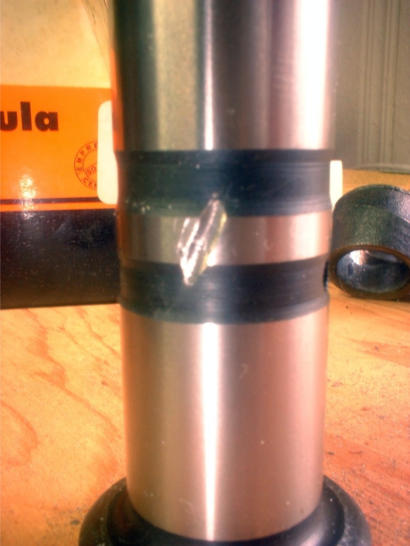
Normally, a VW tappet acts as a valve, and only allows oil to flow from the main gallery to the heads via the hollow pushrods during a short period of time, about 1/8th of the time. There are two problems with this: lubrication, and heat. Not enough oil reaches the valve train to keep the metal bits slipping and sliding happily, and air cooled engines are largely oil-cooled engines - not enough oil reaches the heads to carry off heat from the exhaust valves.
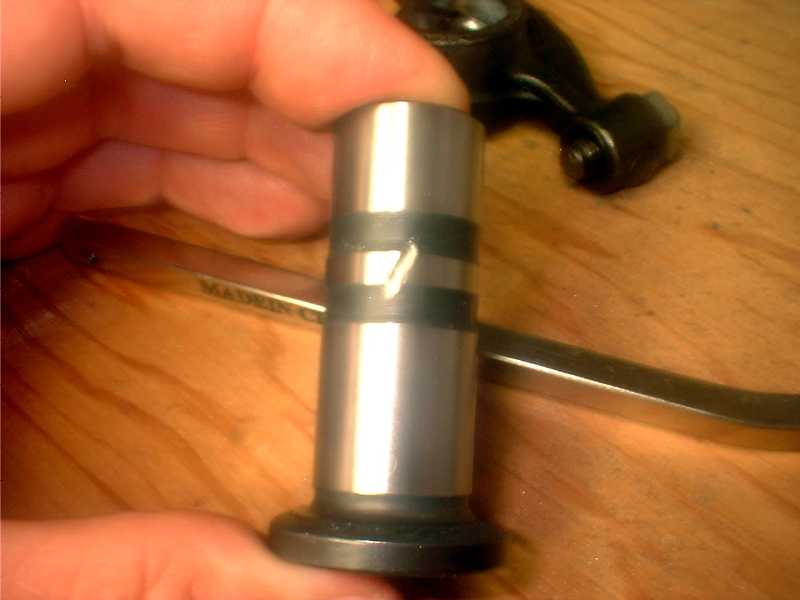
Carving this little groove in the tappet body (typical, arrange 3 of them around the body of the tappet, and for Pete's Sake, use brand new tappets, reground tappets are junk), free-hand, with a round diamond burr in a dremel, allows oil to flow to the heads 100% of the time. It's pretty easy. This is not a job requiring precision, although you don't want to let the Dremel run away from you, and have the burr go skittering across the polished surface of the land between the two grooves. That surface does have to ride against the magnesium bore of the case, and it should be as smooth as you can keep it/get it. Careful workers will protect areas not under immediate Dremel attach with tape. Sloppy ones like me will have at it free-hand, and polish the boo-boos.
|
|
Break the sharp edges of the new groove with a stone, or a diamond lap, and polish with red rouge, and you're done
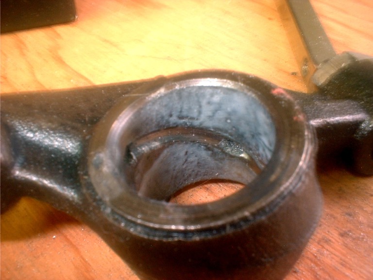
Once the oil gets out to the valve train, it needs to get distributed. Again, the stock bits don't do this too effectively. Well enough to meet Adolf's durability goal (60K miles), but not well enough for your or me flying behind an engine designed in the 1930's. Sorry about this fuzzy picture, but I've already modified all of my rocker arms, and this is my only view of an un-modified stock arm.
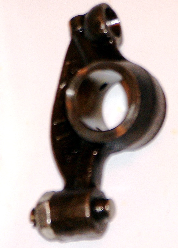 |
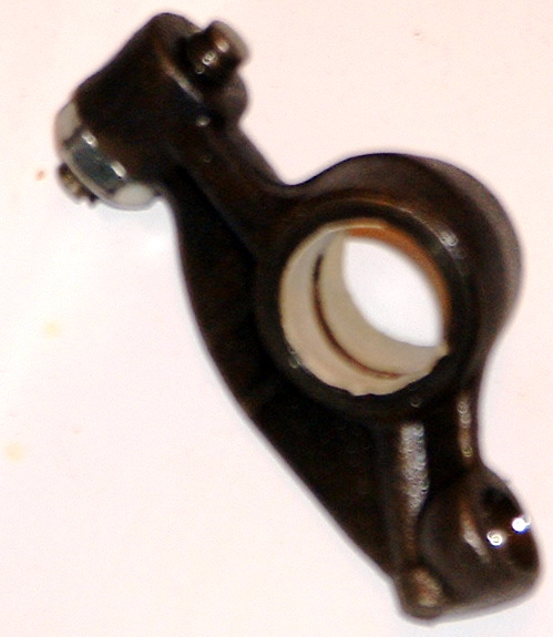
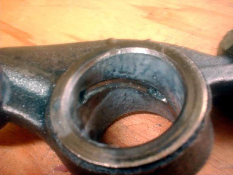
The objective is to connect those two little holes. One brings oil from the pushrod, the other sends it to the adjuster screw, where it dribbles onto the top of the valve stem in pitful amounts, in the stock setup. In the next shot, I've masked the interior of the rocker arm to protect the polished surface from errant yips with the Dremel. |
 |
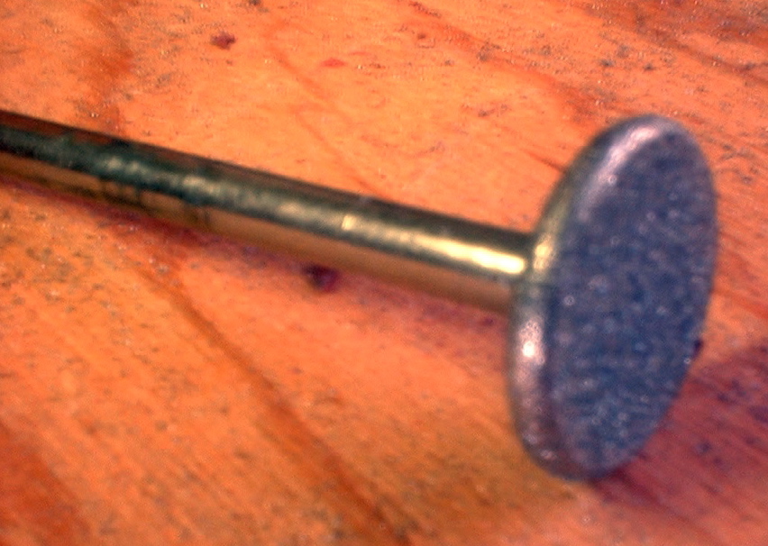
This is the diamond burr you need, which you get from Widget Supply, it's their D-GP08, 1/2 inch x 3/32 inch Round Edge Diamond Coated Wheel $2.49 |
 |
Here is the finished product. I did one set with the tape, and did the other set (you DO have two sets of heads, don't you? You should) freehand, and I can't tell the difference. It's a good bit harder to get into this bore and break the resulting sharp edges. I did my best with red rouge and a felt bob. |
 |
 |
See the micro-swarf hanging out in the oiling holes? Get it out of there by removing the adjusters, and blowing it out. Those gritty little pieces of hardened steel must go, BEFORE engine assembly. |
This entails enlarging the existing oil passages past the #2 bearing, drilling a new passage around the #3 bearing, and deepening the main gallery to hook up with the new oil passage you just drilled.
A fellow dabbler wrote:
> I am planning on doing some of the mods to the case like making oil
passages larger as suggested by hvx mods but the one I am wondering
if I will mess up is the drilling of the new passage below the end
cam bearing along with the horizontal drilling from transmission end
towards the pulley end to match up with the new cam bearing drilled
passage.
> Someone please tell me if this is easily messed up or not before I
attempt it.
Yes, it is possible to mess this up. I tried this on a junk case (pictures are posted in the AirVW Yahoo Group files section). Good thing I did. DO NOT drill any deeper than the drawings Bob provided show, or you will likely break through either into the main part of the sump when drilling from the cam bearing, or out the case when drilling the other way, and you will have an oil leak, either internal or externel, depending on HOW you were stupid. This sort of Boo-boo is semi-repairable, but only by a shop equipped to weld magnesium - like RIMCO, and it will cost plenty.
It's pretty hard to get off line when deepening the main gallery, but it is possible to get off line drilling from the cam bearing. I think between that, and the fact that magnesium chips love to pack together, I couldn't see daylight when I finished drilling to the depth Bob showed us would intersect. So, I drilled a little deeper. You can see where this is going....
So, do this operation with ALL the head studs removed so you can mount the case on the drill press dead nuts flat to drill down from the cam bearing. Use a drill stop. Stop and clear the chips often. Drill down from the cam bearing first, then lengthen the gallery, that will prevent chips from the more critical hole packing the gallery. If you still don't see daylight, stop. Think. Pull everything out, and either use a bore brush or a blow gun to get ALL the chips out before proceeding.
It is actually pretty easy, as far as machining operations go, The long aircraft drill in semi-weird sizes you'll need are not Home Depot items, but you can get them from Travers or Enco. And enlarging the passages around behind the cam bearings is VERY easy, with no downside, and is also illustrated in the pictures I've posted to the AirVW Yahoo Group files section.