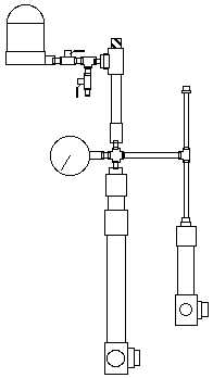
The centrifuge(CF) in the diagram is on the left.
connected to the CF with a close nipple(CN) is a 1/4" stainless steel ball valve(BV)
connected to the BV with a CN is a 1/4" Tee fitting
connected to the 1/4 Tee with a 1/4 to 3/8 and 3/8 to 1/2 and 1/2 to 3/4 bushings is a 3/4 Tee
connected to the 1/4 Tee with a CN is a BV that serves as flow control
connected to the 3/4 Tee is a 6" 3/4 nipple and the flux capacitor() shown in cross hatch.
connected to the 6" nipple is a 3/4 to 1/4 reducing coupling(RC)
connected to the RC with a CN is a Cross(Cx) fitting
connected to the Cx is a pressure gauge and the larger of the two Heating Elements(Ha)
connected to the Cx with another 6" nipple another T fitting
connected to the T is the smaller Heating Element(Hb) and a 6" 1/4 nipple with a cap. This becomes an accumulator.
inside Ha is a 3500 watt water heater element taking 220V
Inside Hb is a 1500 watt element taking 120V
The circles at the bottom of Ha and Hb are the input ports and are connected to the pump