Friday, August 17, 2007

VW Powered Homebuilt Aircraft Accidents

Partisans of various brands of VW aeroengines like the throw stones at each other about the service experience of The Other Team. NTSB reports tell the truth, so here are links to every one I could find mentioning "VW" "Volkswagen" "Aero Vee" "Aerovee" "Great Plains" "Revmaster" "HAPI" "Mosler" "TEC" "Limbach" since 1962 in the NTSB database that seemed to engine related.

Great Plains Powered Mini Imp, sloppy mechanic-ing.


Incredibly sloppy installation.

Revmaster spit a pushrod.

2180 KR-2, apparently quit in flight, who knows why? May have been a Great Plains - HAPI didn't believe in strokers.

Aerovee powered Sonex, shrink fit hub let loose.

Apparently a Revmaster, bad fuel system installation.

??? Chris-Teena engine failed in flight.

Owner overhauled engine failed in less than 25 hours, scored piston walls.

Unknown engine type "...fitted with a guillotine slide type carburetor" failed when throttle closed.

Unknown engine type WAY too lean.

First and last flight of an underpowered VP-1

Dragonfly + a poorly performing carb = one quadraplegic and a pile of junk.See also this site for more on this plane, crash, and the pilot's new life.

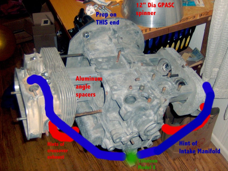
Jack Lockamy's Type IV Sonex, prop hub separated from GPASC/SCAT crank.

Ignition wire failure.

First flight of the first completed Noon Patrol Nieuport, loose distributor clamp. A short between the earlobes.

Ellison TMI and bad gas/neglect.

Rear oil seal failed. HAPI? NOTE: this is a lesson to all: follow the Official VW handbook procedure to install the rear seal! NO RTV! Use the (cheap) special tool to seat it, not a block of wood and a hammer!

Loose throttle cable.

Sloppy hub installation.

No end play = seized engine.

VP-1 engine failed on takeoff.

Bad magneto coil downs Vp-1.

Carb ice on a slide body - they said it couldn't be done. Note: Carb ice was NOT PROVEN; this was the explanation offered by the accident pilot.

??? lost power, crashed. The date and the airframe suggest the previous generation of Aerovee, but that's FAR from proven.

Revmaster unknown power loss, carb ice mentioned as a possibility. There is that impossible slide valve carb ice again, although to be fair, there is no suggestion this airplane has a Revmaster carb, and it WAS fitted with carb heat, which WAS on. Revmaster idea of carb heat however is to pull warm air off the bottom of the case...you come to your own conclusions.

Revmaster almost certainly carb ice. Take a look at the carb heat for a Revmaster. Now, you just took off, in the rain. Think the case will be warm enough to heat the intake air enough to melt the ice?

Loose carburetor jet on a Mosler (formerly HAPI) engine. HAPI Super Carb?

Carb ice on a Mosler, even with carb heat on. POSA (slide valve) carb is likely, but NOT PROVEN.

HAPI engine run too lean, died with the man who built it.

====== CONCLUSIONS ======

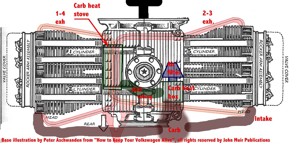
I have long thought, based on physics and very little actual evidence, that running a slide valve carb without TRUE carb heat (from at least two exhaust pipes) is insane. I was a little surprised these reports seem to confirm my THEORETICAL presumption.

There are black marks against ALL vendors, but the is not enough data here to make a call between them. Most of these reports don't identify the conversion vendor.

Most faults seem to be behind the eyeballs of the pilots/builders, and ignition and fuel systems problems are manifestations the bulk of those. Careful attention to Firewall Forward
would have saved a lot of these crashes and pilots. Every word of that book is written in blood.

Labels: ,

Sunday, August 12, 2007

More Progress On Exhaust System

Initial try, wood block represented the (theoretical) cross section of the carb heat stove.
Unfortunately I forgot to account for the pushrod tubes. So the carb heat stove had to get substantially slimmer, and the the 180 degree bends got "clocked" vis-a-vis the exhaust flanges a little bit. I'm using hot melt to hold the bends to the exhaust flanges. It works great, it holds securely enough to get everything jigged up, and breaks lose if you make a boo-boo (the oil on the tubing helps this).

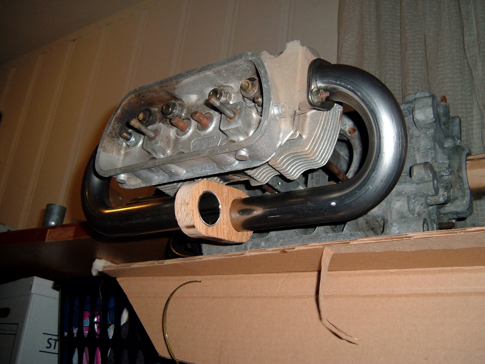
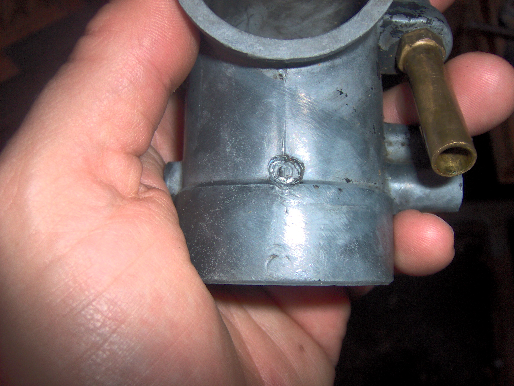
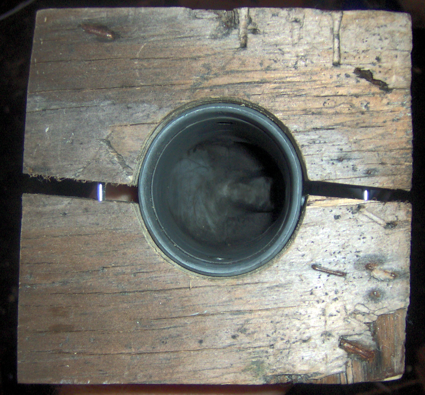
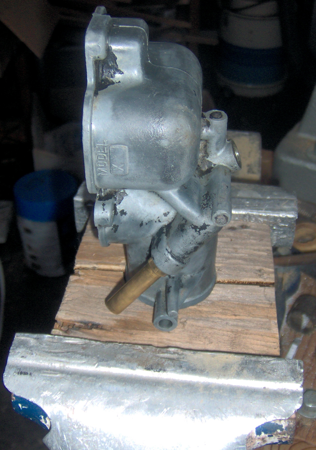
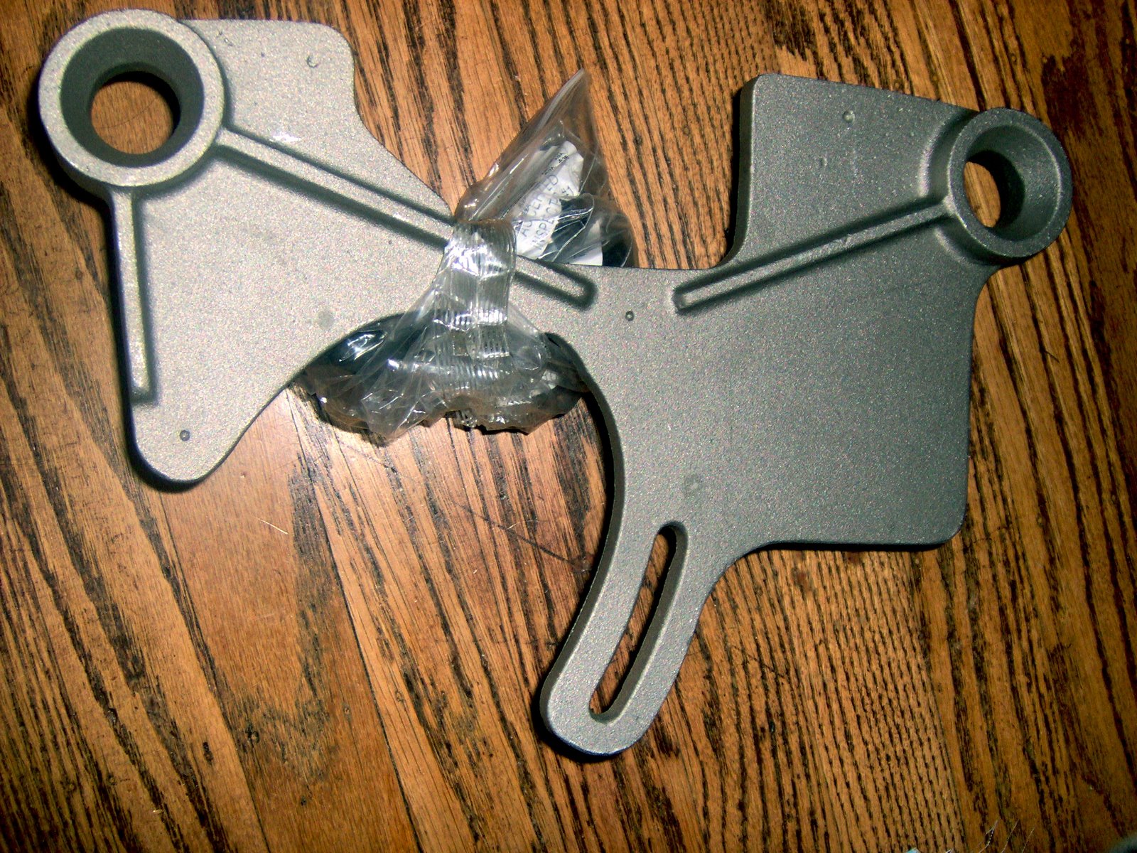
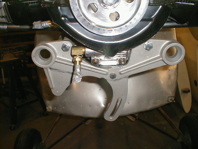
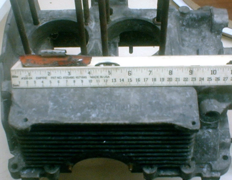
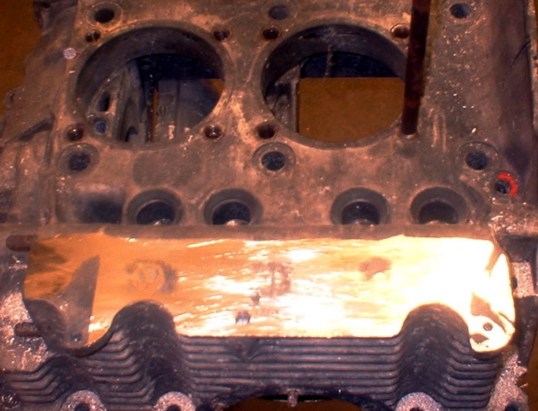
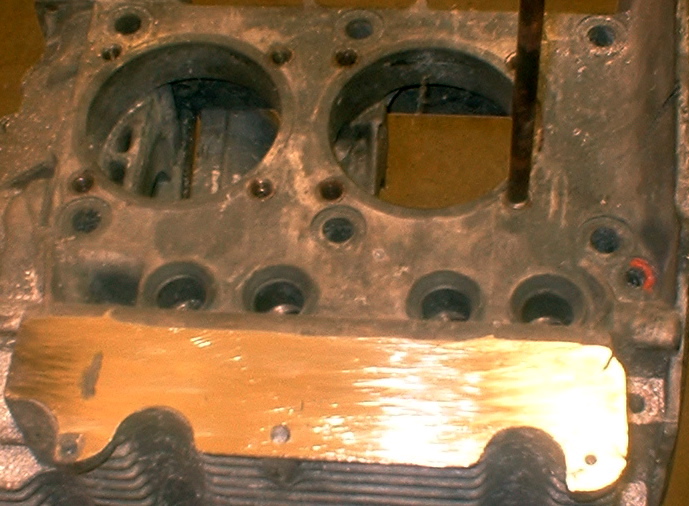
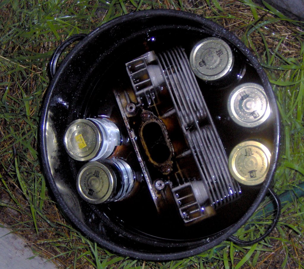
I forget where I stole this idea but it works great! The welder (not me, I'm not currently set up for it) can tack the butts in between the 3 coat hanger wires.

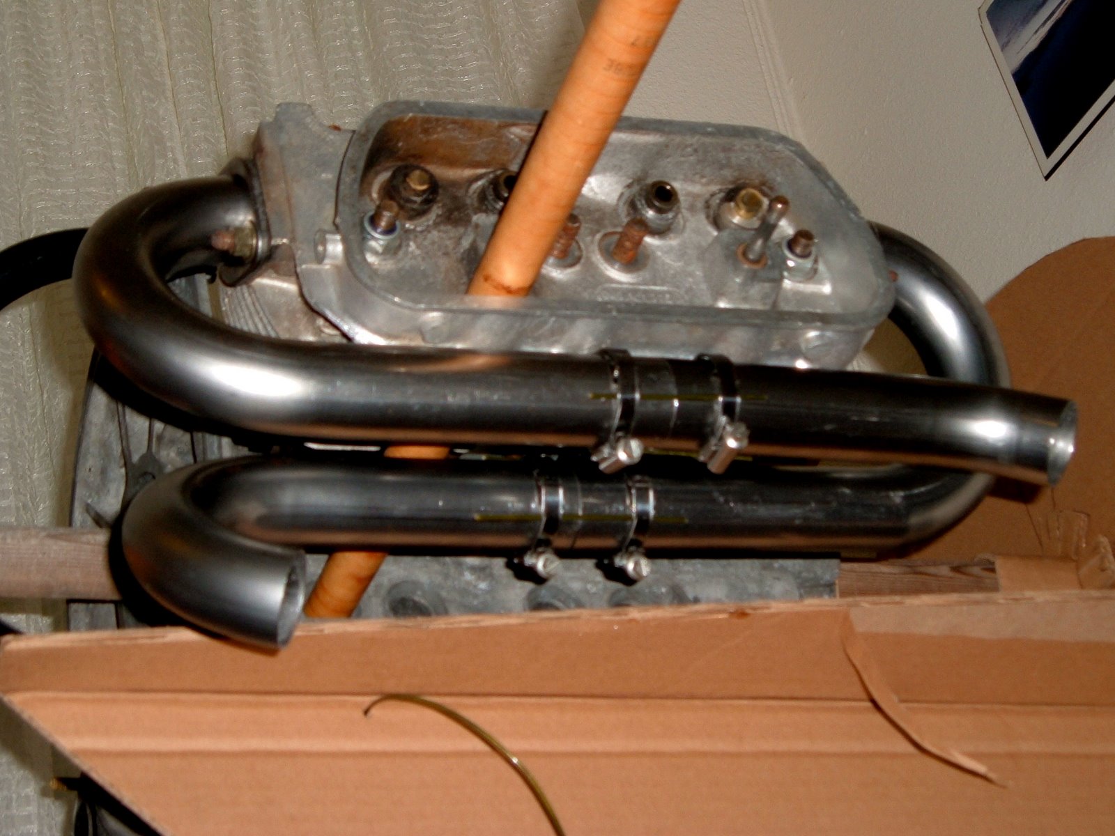
Ready to send to the welder.
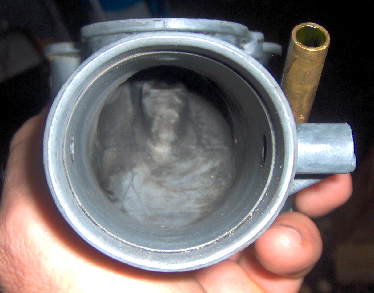
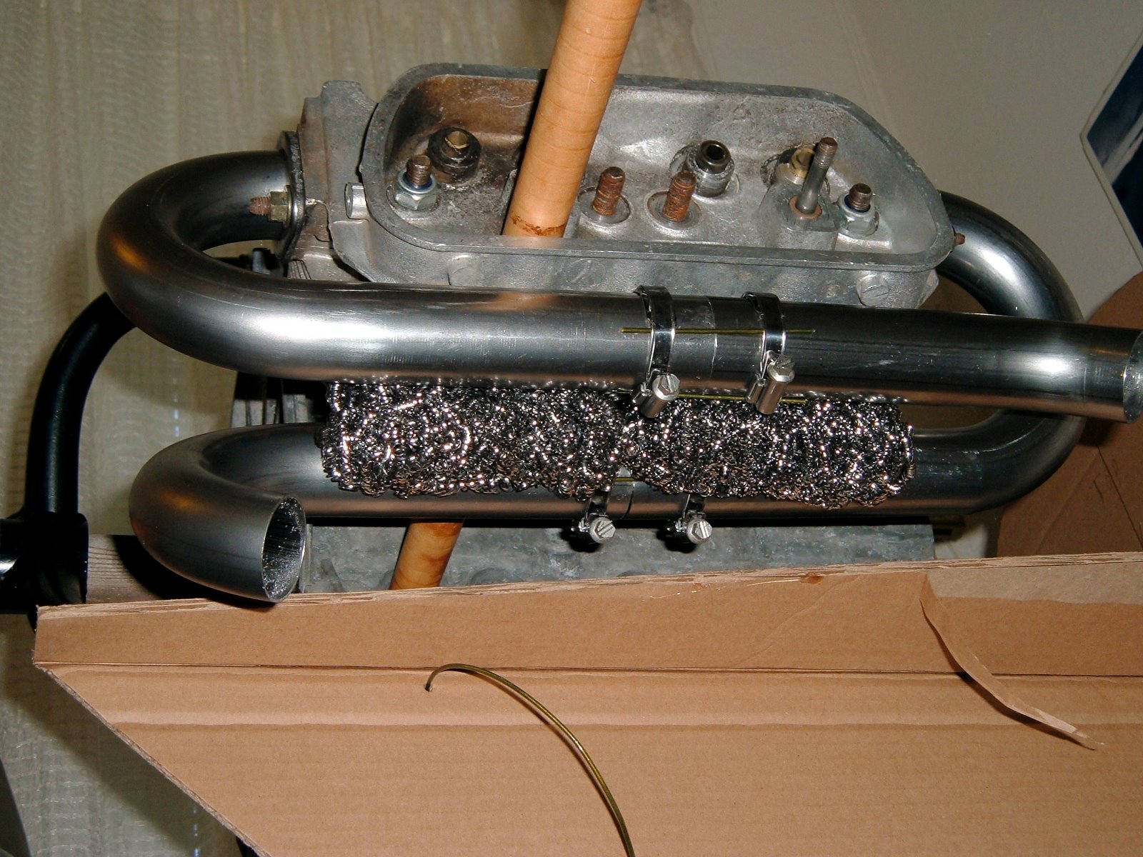
Note the stainless steel pot scrubbers to add heat transfer surface.
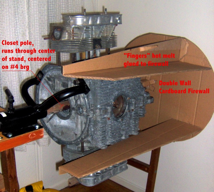
 This entire mess gets wrapped with aluminum sheet, with a flanged connection for the duct to the heat box. Not shown in any of these views is the solid aluminum spacer that gets clamped in between the pipes to hold everything nice and solid. I didn't like how the pipes were cantilevered off the exhaust flanges.

This was a pretty easy and satisfying project. I made all the tubing cuts with a hacksaw, cleaning them up with my disk sander.

The next question is whether to make the other side identical to this, or to go as simple/light as possible, or to join the pipes to facilitate a muffler. I've flipped the engine over in the stand, and I'll stare at it for a few weeks - something will come to me. Also, the plumbing of the hot air to the carb heat box is a little unclear. The bed mounts REALLY get in the way of where I'd like to route this tubing. Hopefully once the intake starts coming together that will be a little clearer

Labels: , ,

Sunday, June 10, 2007

More with the Firewall Forward Mockup


With a double wall cardboard box from the local recycling center, and some hot melt, the spatial relationships of the engine to the front of my fuselage are getting clearer. This design uses a "bed mount". The sides of the case are flattened, and aluminum angles are bolted through the walls of the case. Resilient "Barry Mounts" then bolt up to these "fingers, built up of extrusions and sheet. The reason I chose this airframe is that these mounting scheme doesn't care which way the flywheel faces. The prop hub on this airframe will be mounted on the flywheel end, the left in this image.


Some of the details. Hot melt glue is a great thing for this sort of quick and dirty assemblage.


The pole is centered on the #4 bearing with a cardboard "bushing". Nothing is glued to the pole, allowing it to be taken apart in a pretty tight space here in the corner of my front hall/workshop, and to position the engine relative to the airframe.


It's not too clear in this view, but most of the engine outboard of the case hangs out in the breeze in this design.

Now it's time to start playing around with the tubing bends, and seeing how it will all fit together, if it will.

Labels: , ,

Friday, June 08, 2007

VW Aero Engine Mockup


In order to work out the intake and exhaust, I've built a mockup out of a junk case, 2 junk heads, and some aluminum spacers. I've got it mounted to my engine stand, so I can flip it all around with relative ease. Below is my first cut at what the plumbing will look like:


Symmetry is the hobgoblin of the unimaginative. The objectives here were a crossover 4 into 2 into 1 exhaust, take carb heat off at least 2 cylinders, and have the sump accessible for oil changes. To save weight, the intakes will be fabricated out of aluminum bends from Burns Stainless, the exhaust will be mild steel, starting from a Great Plains U-Build kit, ceramic coated.

Update: I've decided I don't like the 1-4 exhaust running that close to the carb, so I'm going to try to run it in front of the intake.

Another Update: NONE of the exhaust scheme presented here worked at all, given the bed mount of my fuselage, so I've radically simplified the arrangement, so later posts.

Labels: , ,

Tuesday, May 29, 2007

Notes on overhauling a Tillotson Model X Carburator

A Tillotson Model X Stripped Bare

Why bother farting around with a carb that's been out of production for at least 30 years? Well, some think that it's still an excellent choice for a flying VW engine. It's simple, robust, and does a pretty good job, for this size engine, of supplying the right fuel-air mixture over the entire speed range of use, which is about 800 to maybe 3600 RPM max, and that would be pushing it.

I bought a couple of cores, and recently set to work overhauling them. While there is a lot on the web about overhauling Zenith Model A carbs, there is bugger-all on the Tillotsons, which were/are MUCH lighter (Zeniths are CAST IRON), cheaper, and in some ways better.

First, a note about cores. It's best to examine them, or at least get good pictures, with the top cover off. One of my cores looks to be unsalvageable, as the boss for the main jet is broken, right in the throat where it all happens, mixture wise. I might be able to fix this with some JB weld, but for now, it's paperweight. And neither core I bought online had a choke/mixture driver. Not essential for my aviation application - I'll be using a primer to cold start the engine - but if you're building up a car, you'll want one. The OTHER core I bought had it's own problem, it looked like The Jolly Green Giant had stepped on the intake, more no that anon.

Another issue is the overhaul kits. Some are MUCH more complete than others. The $75 kits have damn near everything, including new choke and throttle shafts and butterflies. My $15 kit has the gaskets, jets, float valve, the several needle valves, and not much else. But it's sufficient, with my cores, although I would like to have the smaller passage plugs to be able to clean out EVERYTHING.

Finally, the 13/32 inch wrench you'll need to get the Gas Adjusting Needle Housing out is a rare beast indeed, get a cheap 10mm open end wrench and file it to fit.

Disassembly is pretty self explanatory. If something doesn't want to come apart, soak the whole deal in carb cleaner a day or so before trying it again. You can use a LITTLE heat on the housings, but not much, or you'll have a shiny puddle on the shop floor. Rust is not a problem with Tillotson's, but old dried up gas is pretty effective locking compound. So, back in the dip tank.

Here is the problem I had with my "best" core. What's wrong with these pictures:

Notice the circular crater in the center of the intake horn? (this is the top of the lower casting by the way) Some Brain Donor in the past honked down on the grub screw holding the Air Maze on so hard it ovalized the intake horn itself. It was a lot worse before I took these pictures, I've already pressed it almost back into shape.


Here you can see the bottom of that crater protruding into the ID of the "kirksite" casting, also called "pot metal", a low melting point mixture of zinc and aluminum that is a pretty great material for this sort of casting, as long as you keep it away from salt water. The choke shaft and butterfly plate goes in here, the main jet is way up in there, and the Gas Adjusting Needle Housing is still in this core, it's the brass tube on the right side. I'll use my fancy tooling to get this horn close(r) to round again.
Here's the fancy tooling, a 1 inch thick piece of (hardwood?) plywood scavenged out of an old couch. The idea is to press it back into shape, without putting too much of a point load on the rather brittle casting. Note the "tooling pins", other wise known as common nails with the heads cut off. I use a lot of them. Thanks, R.S Hoover.
Proceed slowly and cautiously please. I only have one good lower casting, and this is more of "Nice To Have" action, as the carb heat box I'm planning to make up soon will be able to accomodate the out-of-roundness that's left at this point.

Most homebuilt carb heat boxes use the nice spun aluminum flanged fittings you can get from Aircraft Spruce. But the Tillotson throat doesn't match any of the available sizes exactly, so I've been scratching my head, and consulting my reference books for a way to custom fabricate such a thing without welding or machine tools. Found it, look at this:
This flanged fitting is two pieces of sheet metal. The inner tube penetrates the wall of the box, presumably into a tight, flycut hole. The outer tube has the flange. It looks like there is a bit of spooj sealing it all up. I can make THAT. The rest of this guy's engine installation looks really good, check it out. And while you're at it, read a little about R.S. Hoover's approach to carb heat boxes, and William Wynne's personal experience on why you need one.

Labels: , ,

Saturday, May 12, 2007

Engine, Alternator mounts for Flywheel Drive VW Aeroengines

Some of us believe the proper way to mount the prop to a VW engine is via the Flywheel end of the engine. Great Plains Aircraft Supply has some around to this way of thinking, and now supplies pieces to make this happen. They have not, as yet, posted very good pictures of the stuff, so I'm stepping in to give out some clues. R.S. Hoover, in the Chuggers and AirVW Yahoo groups, has posted some pictures of the flywheel end piece, and the spool prop extension. On my Hummel Ultracruiser Plus variant, I thought I would be able to use a belt drive to a Kubota/John Deere PM alternator, so I bought one of Steve Bennet's combined alternator/motor mounts.

This side faces the engine. Those little bosses at the top of the image get drilled to clear 8mm fasteners that tap into the existing bosses on the case itelf. The two big holes service conical shock mount bushings, with interface with a bed-type engine mount.

Similarly, this face gets drilled for the pivot point for the alternator, and another fastener to the case. The holes are nicely located, with a cast in "Center Punch".

Unfortunately, this part will NOT work on my fuselage, as the extensions of the forward fuselage that form form the the engine mounts on this design don't leave enough width for this dealy. Steve took it back with no questions.

This piece was designed to be part of the Great Plains Rear Drive System, which involves an outboard thrust/radial bearing, which the Flywheel Drive setup DOES NOT use. The casting Steve devised for this setup has similar conical bushing bosses cast in. Here is a picture of such an installation on Hal Hadaller's airplane:

The mount mounted. Note the tight clearance to the oil pump outlet.


Hal ended up with the alternator in a different place, so he cut off the arm for adjusting it from the mount.

Here's the whole RDS deal installed on the firewall:

Compare/Contrast to this Flywheel Drive setup on a Sonerai:

R.S. Hoover is one advocate of Flywheel drive, having flown several planes with it, and Chad Stenson is another, with airplanes flying using it. You can find R.S. Hoover via various Yahoo groups, and Chad via Sonerai.Net. I haven't flown this hardware, but I'm building such an engine right now.

Labels: , ,

Engine Mounts for Hummels

Hummel Aviation uses a rather unique method of mounting either a half or a full VW engine in their designs. Rather than the usual "Conical" mount (usually via an accessory case), they bolt a couple of aluminum angles to the sides of the oil sump, and work shock mounts from there.
It's a bit of a chore to do this accurately. Scott Casler, the Hummel Engines guy suggests using a belt sander. Not having one, I used a vixen file, and a lot of swearing.

Here we begin.

Notice the "sugary" surface is getting brighter and brighter.


I used prussian blue and a section of aluminum plate as a surface plate to keep the surface flat, getting there.

I think it's time to declare victory. This is a junk case I use for experimenting, by the way.

This is what the inside of the case looks like. The bolt heads (AN4) have to fit down in those cavities, which are not exactly flat. I'd love to spotface in that area, but it's a PITA, and the sump walls are only about .200 in thick, so you don't want to carve away too much meat.

The solution, as far as I'm concerned, is a clever little dealie called a Stat-o-Seal. It's an aluminum (and therefore deformable) washer, with an o-ring bonded to the ID.
Between the O-ring, and the crush washer, we should achieve a good mecanical connection, and a seal the oil in the case. The aluminum angles will get a coat of whatever case sealer my engine builder likes. Self locking nuts go on the outside.

Labels: , ,

Sunday, November 26, 2006

Cleaning your heads

Air cooled VW heads are aluminum; if you "hot tank" them, all you'll be left with will be the studs, valve guides, and seats. You need to cold tank them. Shops around here charge $40 just to cold tank the heads.

Radiator Specialty Company, the makers of GUNK, sell a suitable "digester", that eats anything carbonaceous, and leaves the metal untouched. There is at least one other brand, with different chemistry. The problem is getting anybody in California to sell you any, particularly since your head won't fit in the little dip tank. You need at least 2 gallons, and container that's at least 13 X 10 X 8 Inches, with NO plastic anywhere.

I bought the last gallon of GUNK Carburetor Cleaner the local Kragen had on the shelf, then went back to get another, and not only didn't they have it, they claimed to be unable to get it. Radiator Specialties also makes a product called Hydro Seal II, which is available in useful larger quantities, but it apparently cannot be retailed in California at all.

Girlfriend's enameled Canner served as the Cold Tank, and was able to score the second gallon at a DIFFERENT Kragens (total cost for parts cleaner = over $40 - should have Paid The Man - Oh Well). Still wasn't enough to cover the heads, so I filled some tall glass jars with water to displace some volume, and then added a little more mineral spirits. This toxic brew lives under the porch, WITH THE LID ON, the shade keeping it from getting too hot, and sending Volatile Organic Compounds skyward.

In a month or two, I'll fish out the first head, and put the second one in. Then we'll inspect them, and start rebuilding them, if they are worthy.

UPDATE 11/08
The heads were junk, not worth rebuilding, but they live on in the engine mockup.

Labels: ,